
Embark on a journey into the fascinating realm of AC Theory Level 2 Lesson 8, where we unravel the intricacies of alternating current. This lesson serves as a gateway to understanding the fundamental concepts, components, and applications of AC circuits, paving the way for a deeper comprehension of electrical systems.
As we delve into the heart of AC theory, we will explore the building blocks of AC circuits, examining the roles of resistors, capacitors, and inductors. We will uncover the relationships between voltage, current, and resistance in these circuits, gaining insights into their behavior under alternating current conditions.
Overview of AC Theory Level 2 Lesson 8
Lesson 8 of AC Theory Level 2 delves into the intricate world of three-phase circuits. Understanding these concepts is crucial for electricians, engineers, and anyone working with AC power systems. By mastering these principles, individuals can effectively analyze, design, and troubleshoot three-phase circuits, ensuring safe and efficient operation.
This lesson covers the following key concepts:
- Three-phase power systems and their advantages
- Phase sequence and its significance
- Power measurement in three-phase circuits
- Balanced and unbalanced three-phase systems
- Three-phase transformers and their applications
Three-Phase Power Systems
Three-phase power systems consist of three alternating currents (AC) that are offset by 120 electrical degrees. This arrangement offers several advantages over single-phase systems, including:
- Increased power transmission capacity
- Reduced line losses
- Smoother torque in motors
- Elimination of neutral current
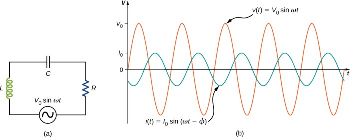
AC Circuits and Components
In an AC circuit, alternating current flows through a combination of resistors, capacitors, and inductors. These components play crucial roles in determining the behavior of the circuit.
Types of AC Circuits, Ac theory level 2 lesson 8
- Series Circuit:Components are connected in a single loop, so the current is the same throughout the circuit.
- Parallel Circuit:Components are connected in multiple branches, so the current can take different paths.
Functions of AC Circuit Components
- Resistors:Oppose the flow of current, causing a voltage drop.
- Capacitors:Store electrical energy in an electric field, opposing changes in voltage.
- Inductors:Store electrical energy in a magnetic field, opposing changes in current.
Relationships in AC Circuits
In AC circuits, the relationships between voltage, current, and resistance are more complex than in DC circuits due to the presence of reactive components (capacitors and inductors).
- Ohm’s Law:V = IR (still applies, but impedance replaces resistance in AC circuits).
- Impedance:A measure of the total opposition to current flow, considering both resistance and reactance.
- Phase Angle:The difference in phase between voltage and current, influenced by the reactive components.
AC Power and Power Factor
AC power is the rate at which electrical energy is transferred in an alternating current (AC) circuit. It is measured in watts (W) and is calculated as the product of the root mean square (RMS) voltage, RMS current, and the power factor.
Power factor is a dimensionless quantity that represents the ratio of the real power (the power that does useful work) to the apparent power (the total power supplied to the circuit). It is expressed as a decimal between 0 and 1.
Methods for Improving Power Factor
Improving power factor is important because it reduces losses in transmission lines and improves the efficiency of electrical systems. Methods for improving power factor include:
- Capacitor banks:Capacitors can be added to the circuit to cancel out the inductive reactance and improve the power factor.
- Synchronous condensers:Synchronous condensers are rotating machines that can be used to generate or absorb reactive power, thereby improving the power factor.
- Static VAR compensators (SVCs):SVCs are electronic devices that can quickly adjust the reactive power output to improve the power factor.
AC Transformers
AC transformers are devices that transfer electrical energy from one circuit to another through electromagnetic induction. They are used to change the voltage and current levels of an AC signal, making them essential components in power distribution systems.
The basic principle of operation of an AC transformer involves two coils of wire, known as the primary and secondary windings, wound around a laminated iron core. When an alternating current flows through the primary winding, it creates a changing magnetic field in the core.
This magnetic field induces an electromotive force (EMF) in the secondary winding, which causes an alternating current to flow in the secondary circuit.
Types of AC Transformers
There are various types of AC transformers, each designed for specific applications:
- Power transformers: Used to step up or step down voltage levels in power distribution systems.
- Distribution transformers: Smaller transformers used to distribute power to homes and businesses.
- Instrument transformers: Used to measure voltage and current in electrical circuits.
- Isolation transformers: Provide electrical isolation between two circuits, preventing the flow of current from one circuit to another.
- Autotransformers: Have only one winding that serves as both the primary and secondary windings, providing voltage regulation.
Factors Affecting Transformer Efficiency
The efficiency of an AC transformer is influenced by several factors:
- Core losses: Energy lost due to hysteresis and eddy currents in the iron core.
- Copper losses: Energy lost due to the resistance of the windings.
- Leakage flux: Magnetic flux that does not link both windings, resulting in energy loss.
- Load factor: The ratio of the actual load to the rated load, which affects the transformer’s operating temperature and efficiency.
AC Motors and Generators
AC motors convert electrical energy into mechanical energy, while AC generators convert mechanical energy into electrical energy. Both devices rely on the principle of electromagnetic induction to function.
Principle of Operation
In an AC motor, a rotating magnetic field is created by passing alternating current through a stator winding. This rotating field induces an electromotive force (EMF) in the rotor windings, causing them to carry current and produce their own magnetic field.
Ac theory level 2 lesson 8 delves into the intricacies of alternating current, providing a solid foundation for understanding electrical systems. If you’re seeking additional insights into human geography, don’t miss the comprehensive analysis of ap human geo unit 4 frq . Returning to ac theory level 2 lesson 8, it’s crucial to grasp the concepts of inductance and capacitance to fully comprehend the behavior of ac circuits.
The interaction between the stator and rotor fields produces torque, causing the rotor to rotate.
In an AC generator, the reverse process occurs. Mechanical energy is applied to the rotor, causing it to rotate. The rotating rotor field induces an EMF in the stator windings, which is then connected to an external circuit to provide electrical power.
Types of AC Motors and Generators
- Induction motors: These are the most common type of AC motor, known for their simplicity, reliability, and low cost. They are widely used in industrial and commercial applications.
- Synchronous motors: These motors run at a constant speed synchronized with the frequency of the AC supply. They are used in applications requiring precise speed control, such as in generators and clocks.
- DC motors: These motors run on direct current (DC) and can be used as both motors and generators. They offer high torque at low speeds and are commonly used in automotive and robotics applications.
- Alternators: These generators produce alternating current (AC) and are commonly used in automotive and power generation applications. They are more efficient than DC generators at higher speeds.
Factors Affecting Motor and Generator Performance
- Load: The load on the motor or generator affects its speed, torque, and efficiency.
- Voltage: The voltage applied to the motor or generator affects its speed and torque.
- Frequency: The frequency of the AC supply affects the speed of AC motors and generators.
- Temperature: High temperatures can affect the performance and lifespan of motors and generators.
AC Measurement and Instrumentation: Ac Theory Level 2 Lesson 8
AC circuits and components can be measured using various methods and instruments. Understanding these methods and instruments is crucial for accurate measurements and safe operation of AC circuits.
Measuring AC Voltage and Current
Measuring AC voltage and current accurately requires the use of instruments designed specifically for AC circuits. These instruments typically employ a rectifier to convert the AC signal into a DC signal, which can then be measured using a voltmeter or ammeter.
Measuring AC Power
Measuring AC power involves determining the power consumed by a load in an AC circuit. This is typically done using a wattmeter, which measures the voltage and current and calculates the power using the formula P = VI cos(θ), where θ is the phase angle between voltage and current.
Types of AC Measuring Instruments
- Analog Meters:These instruments use a moving needle to indicate the measured value. They are typically less accurate than digital meters but are often preferred for their simplicity and low cost.
- Digital Meters:These instruments display the measured value on a digital display. They are more accurate than analog meters and offer additional features such as data logging and storage.
- Clamp Meters:These instruments measure current without breaking the circuit. They are convenient for measuring current in live circuits.
Safety Precautions
When working with AC circuits, it is important to observe safety precautions to avoid electrical shocks and other hazards. These precautions include:
- Always verify the circuit is de-energized before working on it.
- Use proper personal protective equipment (PPE), including insulated gloves and safety glasses.
- Never touch exposed conductors or terminals.
- Use a non-contact voltage tester to verify the circuit is de-energized.
- Be aware of the potential for arcing and take appropriate precautions.
Essential FAQs
What is the significance of power factor in AC circuits?
Power factor measures the efficiency of AC power transmission. A low power factor indicates that the circuit is consuming more reactive power than real power, resulting in higher energy losses and reduced efficiency.
How do AC transformers work?
AC transformers transfer electrical energy from one circuit to another through electromagnetic induction. They consist of two coils of wire, a primary coil and a secondary coil, wound around a laminated iron core. When an alternating current flows through the primary coil, it creates a changing magnetic field that induces an alternating current in the secondary coil.
What are the different types of AC motors?
There are various types of AC motors, including synchronous motors, induction motors, and brushless DC motors. Each type has its own unique characteristics and applications. Synchronous motors maintain a constant speed under varying loads, while induction motors are self-starting and have a high starting torque.
Brushless DC motors are known for their high efficiency and low maintenance.
